
You can use the "Plate Cut" component to cut plates (for example, gusset plates, fin plates, and so on). There are various cutting methods available:
- Plane: The cut is performed on the closest surface to the reference plate.
- Surface: Only the intersecting parts of plates are cut.
- Bounding Box: The outermost dimension consisting of width and height is cut out of the plate as a rectangle.
- Convex Envelope: The outer hull of the cross-section is used for the plate cut. If there are fillets at the corner nodes of the cross-section, the cut is adapted to them.
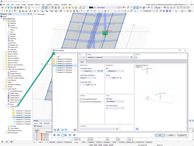
Create guidelines with or without a description for the display of a building grid! You can lock the guideline position to prevent accidental movement of them, for example.
Furthermore, you can glue the guidelines to nodes in order to move the glued nodes as well. That makes your work a lot easier!
Go to Explanatory Video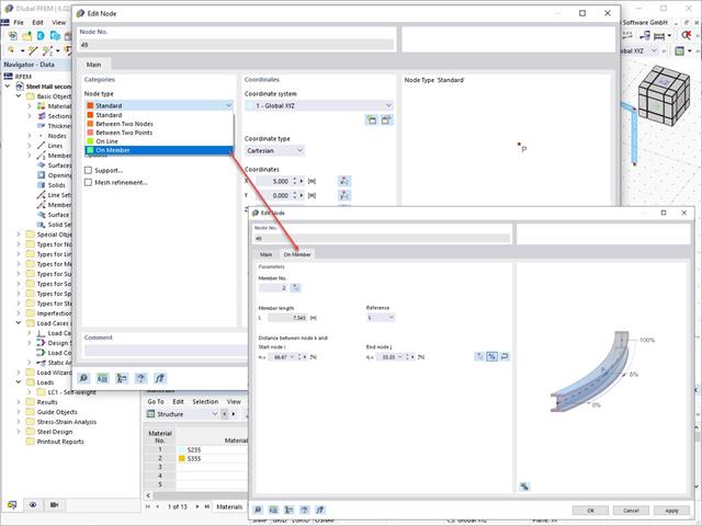
Use the Edit Nodes function to adjust the node type with the automatic specification of all necessary secondary properties. You also have the option to transfer a node to a line or to a member, or to place it between two nodes and two points.

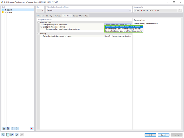
Do you work with the structural components consisting of slabs? In that case, you have to perform the shear force design with the requirements of punching shear design, for example, according to 6.4, EN 1992‑1‑1. In addition to floor slabs, you can also design foundation slabs in this way.
In the Ultimate Configuration for concrete design, you can define the punching design parameters for the selected nodes.

When calculating the deflection limit, you have to consider certain reference lengths. You can define these reference lengths and the segments to be checked independently of each other, depending on the direction. For this, define design supports at the intermediate nodes of a member and assign them to the respective direction for the deformation analysis. Thus, the segments are created where you can define a precamber for each direction and segment.

In the "Deflection and Design Support" tab under "Edit Member", the members can be clearly segmented using optimized input windows. Depending on the supports, the deformation limits for cantilever beams or single-span beams are used automatically.
By defining the design support in the corresponding direction at the member start, member end, and intermediate nodes, the program automatically recognizes the segments and segment lengths to which the allowable deformation is related. It also automatically detects whether it is a beam or a cantilever due to the defined design supports. The manual assignment, as in the previous versions (RFEM 5), is no longer necessary.
The "User-Defined Lengths" option allows you to modify the reference lengths in the table. The corresponding segment length is always used by default. If the reference length deviates from the segment length (for example, in the case of curved members), it can be adjusted.

Have you already discovered the tabular and graphical output of masses in mesh points? That's right, this is also part of the modal analysis results in RFEM 6. This way, you can check the imported masses that depend on various settings of the modal analysis. They can be displayed in the Masses in Mesh Points tab of the Results table. The table provides you with an overview of the following results: Mass - Translational Direction (mX, mY, mZ), Mass - Rotational Direction (mφX, mφY, mφZ), and the Sum of Masses. Would it be best for you to have a graphical evaluation as quickly as possible? Then you can also graphically display the masses in mesh points.

- The proposed connection can be applied to all selected nodes in the structure
- The location of the connection can be defined using the 'Main' tab of the Add-on dialog box
- The design is performed for all connections in the structure and after the calculation, the results on all connections can be displayed
- The table shows the results for the individual connections, each connection is designed and can be saved separately

Did you know? You can individually define the reference lengths to be considered in the calculation of the deflection limit value and the segments to be checked, depending on the direction. For this, define design supports at the intermediate nodes of a member and assign them to the respective direction for the deformation analysis. In the resulting segments, you can also define a precamber for each direction and segment.
You can individually define all reference lengths that need to be considered in the calculation of the deflection limit value, as well as the segments to be checked, depending on the direction. For this, define design supports at the intermediate nodes of a member and assign them to the respective direction for the deformation analysis. Thus, the segments are created where it is possible to define a precamber for each direction and segment.

- For a new connection model, you have to select a node in the RFEM model
- After selecting a node, the members connected to the node are automatically recognized and assigned
- In the window for assigning members, select the ones that will be assigned to the connection
- The members marked by us are displayed in the preview window on the right
- Connections can be modeled for multiple nodes in a structure.
- For member settings, select the ones to be supported
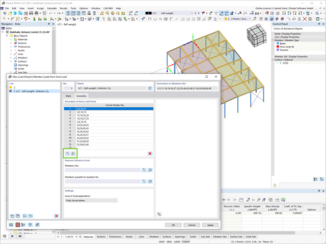
Another useful features in the Load Wiyard is the determination of member loads from area loads by defining surfaces (using corner nodes) and cells in a definition.
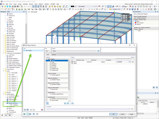
This feature creates more order. The new guide object "Object Selection" allows for generic filtering of various objects:
- Basic Objects
- Types for Nodes
- Types for Lines
- Types for Surfaces
- Load Wizards
- Loads
- Guide Objects
The object selection provides you with many interactive application possibilities at various program locations.
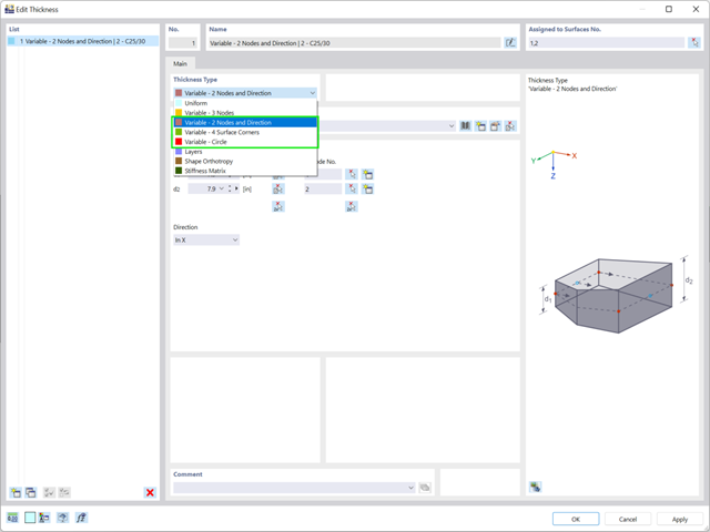
If you want to define variable surface thicknesses, there are three new options available for you:
- 2 Nodes and Direction
- 4 Surface Corners
- Circle
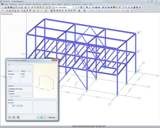
It is possible to selectively display or hide various objects such as nodes, members, supports, and others. The model can be dimensioned by using lines, arcs, inclinations, or height elevations. Freely created guidelines, sections, and comments facilitate the input and evaluation. You can also display or hide the guide objects individually.
Go to Explanatory Video
- Selection of nodes in the RFEM model, automatic recognition and assignment of the members connected to the node
- Many predefined components available for easy input of typical connection situations (for example, end plates, cleats, fin plates)
- Universally applicable basic components (plates, welds, auxiliary planes) for entering complex connection situations
- No manual editing of the FE model required by the user, the essential calculation settings can be changed via the configuration settings
- Automatic adaptation of the connection geometry, even if the members are subsequently edited, due to the relative relation of the components to each other
- Parallel to the input, a plausibility check is carried out by the program to quickly detect missing input or collisions, for example
- Graphical display of the connection geometry that is updated in parallel with the input

- Automatic consideration of masses from self-weight
- Direct import of masses from load cases or load combinations
- Optional definition of additional masses (nodal, linear, or surface masses, as well as inertia masses) directly in the load cases
- Optional neglect of masses (for example, mass of foundations)
- Combination of masses in different load cases and load combinations
- Preset combination coefficients for various standards (EC 8, SIA 261, ASCE 7,...)
- Optional import of initial states (for example, to consider prestress and imperfection)
- Structure Modification
- Consideration of failed supports or members/surfaces/solids
- Definition of several modal analyses (for example, to analyze different masses or stiffness modifications)
- Selection of mass matrix type (diagonal matrix, consistent matrix, unit matrix), including user-defined specification of translational and rotational degrees of freedom
- Methods for determining the number of mode shapes (user-defined, automatic - to reach effective modal mass factors, automatic - to reach the maximum natural frequency - only available in RSTAB)
- Determination of mode shapes and masses in nodes or FE mesh points
- Results of eigenvalue, angular frequency, natural frequency, and period
- Output of modal masses, effective modal masses, modal mass factors, and participation factors
- Masses in mesh points displayed in tables and graphics
- Visualization and animation of mode shapes
- Various scaling options for mode shapes
- Documentation of numerical and graphical results in printout report

In the modal analysis settings, you have to enter all data that are necessary for the determination of the natural frequencies. These are, for example, mass shapes and eigenvalue solvers.
The Modal Analysis add-on determines the lowest eigenvalues of the structure. Either you adjust the number of eigenvalues or let them determined automatically. Thus, you should reach either effective modal mass factors or maximum natural frequencies. Masses are imported directly from load cases and load combinations. In this case, you have the option to consider the total mass, load components in the global Z-direction, or only the load component in the direction of gravity.
You can manually define additional masses at nodes, lines, members, or surfaces. Furthermore, you can influence the stiffness matrix by importing axial forces or stiffness modifications of a load case or load combination.
RFEM supports you and save you a lot of work. The materials and surface thicknesses defined in RFEM are already preset in the Concrete Design add-on. Thus, you can directly define the nodes to be designed.
Any openings in the area with risk of punching shear are automatically taken into account in the RFEM model. The add-on recognizes the position of the nodes of punching shear and automatically determines whether it is a node of punching shear in the center of the slab, on the edge of the slab, or in a slab corner. Again, you save your time.
You can individually select the method for determining the load increment factor β.

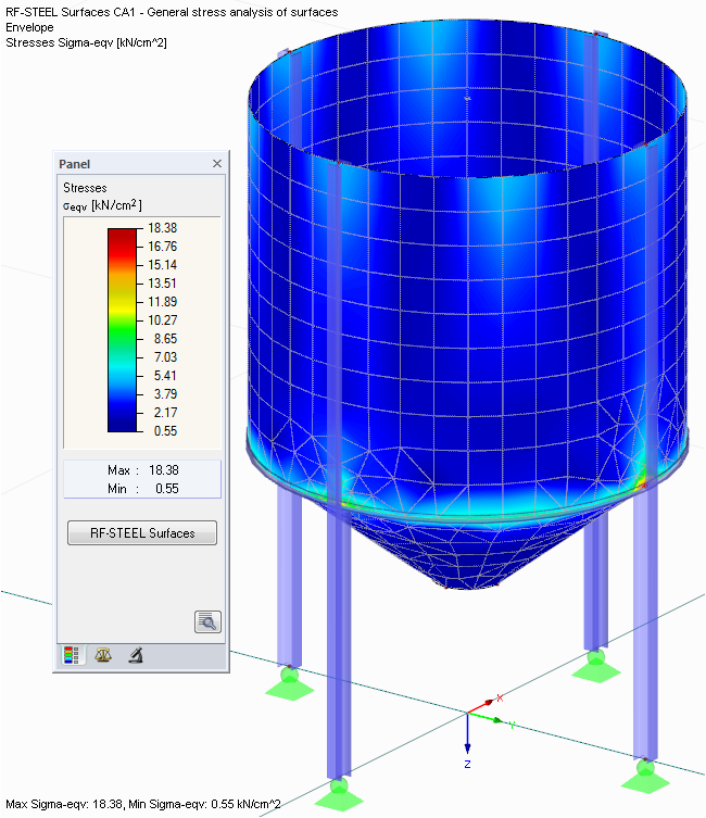
- Determination of principal and basic stresses, membrane and shear stresses, as well as equivalent stresses and equivalent membrane stresses
- Stress analysis for structural surfaces including simple or complex shapes
- Equivalent stresses calculated according to different approaches:
- Shape modification hypothesis (von Mises)
- Shear stress hypothesis (Tresca)
- Normal stress hypothesis (Rankine)
- Principal strain hypothesis (Bach)
- Optional optimization of surface thicknesses and data transfer to RFEM
- Output of strains
- Detailed results of individual stress components and ratios in tables and graphics
- Filter function for solids, surfaces, lines, and nodes in tables
- Transversal shear stresses according to Mindlin, Kirchhoff, or user-defined specifications
- Stress evaluation for welds at connection lines between surfaces (see the Product Feature)
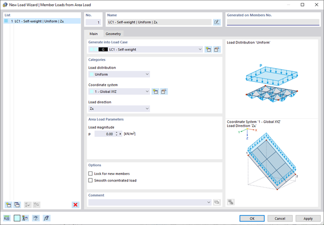
Use all types of loads without any difficulty. You can automatically convert the area loads into member loads or line loads (RFEM).
In the case of member loads from area loads, you have to define a plane via corner nodes or select cells in the graphic. Then the rest works by itself.
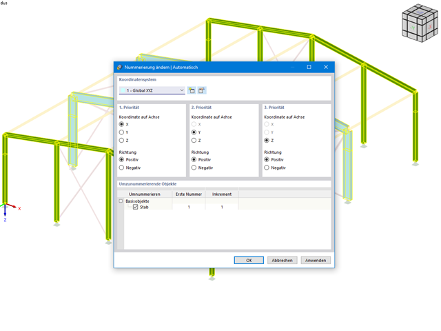
This feature helps you stay flexible in your planning. You can subsequently adjust the numbering of structural objects, such as nodes and members. In this case, it is possible to renumber the objects automatically in accordance with the selected priorities (axis directions).
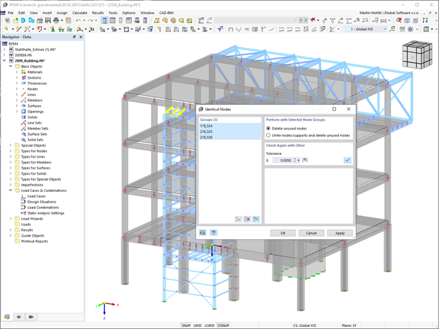
Always keep track of your model. The model check quickly detects for you the input errors, such as overlapping members or identical nodes. You can automatically connect intersecting members during your input. Members can also be extended or divided graphically. The measure function allows you to determine lengths and angles of members and surfaces (only RFEM).
Work more efficiently by freely adjusting the display of your model. You can selectively display or hide various objects, such as nodes, members, supports, and others. Dimension your model by using lines, arcs, inclinations, or height elevations. Freely created guidelines, sections, and comments facilitate you the input and evaluation. You can also display or hide the guide objects individually.
Go to Explanatory Video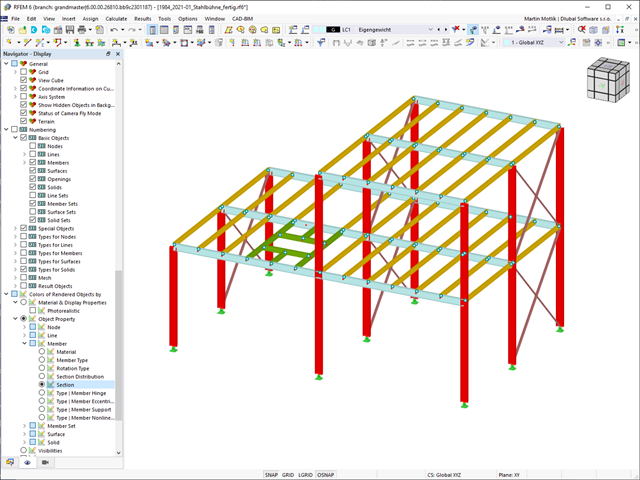
It is possible to assign different colors to various objects of a structure in order to make the rendering display of the structure more clearly arranged.
A distinction is made between the various object properties of nodes, lines, members, member sets, surfaces, and solids. Moreover, the model can be displayed in photorealistic rendering.
Go to Explanatory Video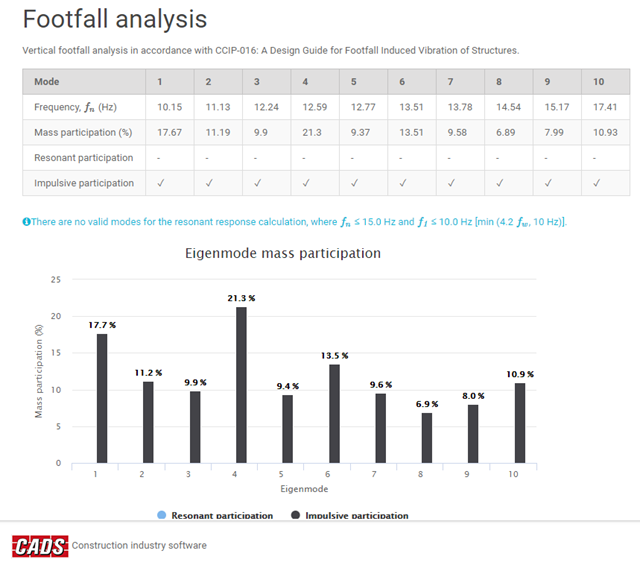
- Overall maximum response factors and critical nodes
- Resonant analysis (maximum response factor, RMS acceleration, critical node, critical frequency)
- Impulsive (transient) analysis (maximum response factor, peak acceleration/velocity, RMS acceleration/velocity, critical node, critical frequency)
- Vibration dose values for both resonant and impulsive analyses
Charts
- Response factor vs walking frequency
- Mass participation vs eigenmodes
- Velocity time history
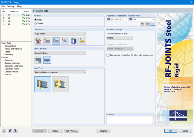
After starting the module, the joint group (rigid joints) is selected first, followed by joint category and joint type (rigid end plate connection or rigid splice plate connection). The nodes to be designed are then selected from the RFEM/RSTAB model. RF-/JOINTS Steel - Rigid automatically recognizes the joint members and determines from its location whether they are columns or beams. The user can intervene here.
If certain members are to be excluded from the calculation, they can be deactivated. Structurally similar connections can be designed for several nodes at the same time. Loads require selection of the governing load cases, load combinations, or result combinations. Alternatively, you can enter the cross‑section and load data manually. In the last input window, the connection is configured step by step.
- Determination of principal and basic stresses, membrane and shear stresses, as well as equivalent stresses and equivalent membrane stresses
- Stress analysis for structural surfaces including simple or complex shapes
- Equivalent stresses calculated according to different approaches:
- Shape modification hypothesis (von Mises)
- Shear stress hypothesis (Tresca)
- Normal stress hypothesis (Rankine)
- Principal strain hypothesis (Bach)
- Optional optimization of surface thicknesses and data transfer to RFEM
- Serviceability limit state design by checking surface displacements
- Detailed results of individual stress components and ratios in tables and graphics
- Filter function for surfaces, lines, and nodes in tables
- Transversal shear stresses according to Mindlin, Kirchhoff, or user-defined specifications
- Parts list of designed surfaces
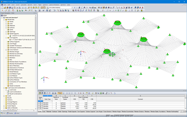
The results of the form‑finding process are a new shape and corresponding inner forces. The usual results, such as deformations, forces, stresses, and others can be displayed in the RF‑FORM‑FINDING case.
This prestressed shape is available as the initial state for all other load cases and combinations in the structural analysis.
For more ease when defining load cases, the NURBS transformation can be used (Calculation Parameters/Form-Finding). This feature moves the original surfaces and cables into position after form‑finding.
By using the grid points of surfaces or the definition nodes of NURBS surfaces, free loads can be situated on selected parts of the structure.
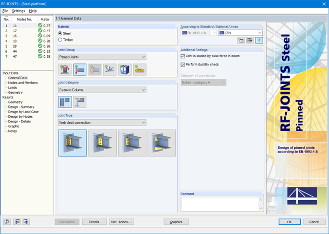
After opening the add-on module, it is necessary to select the joint group (Pinned Joints), then the joint category and joint type (web cleat, fin plate, short end plate, end plate with cleat). Then, you can select the nodes for design in the RFEM/RSTAB model. RF-/JOINTS Steel - Pinned automatically recognizes the joint members and determines from its location whether they are columns or beams.
It is possible to exclude particular members from the calculation, if required. Structurally similar connections can be designed for several nodes at the same time. Loads require selection of the governing load cases, load combinations, or result combinations. Alternatively, you can enter the cross‑section and load data manually. In the last input window, the connection is configured step by step.